While choosing components for the 3″ drone build, we noticed there wasn’t much data for the specific propellers and motors that we were considering.
Looking at existing projects and products on the market, we also noticed that not many of them enabled the collection of the mechanical torque data produced by the drivetrain. The RCbenchmark 1580/5 test stand seemed to be the only product available that recorded rotation speed, thrust, and torque, but this had a high cost of $625-845, depending on the configuration.
This is why we wanted to build a simple-to-use, low-cost thrust stand that could be easily assembled with off-the-shelf components and a few 3D printed parts.
Analysis of Existing Products
Here is a document that compares existing thrust stand products/ projects.
- The RCbenchmark 1580/5 uses 3 load cells: two of which are placed parallel and one (at the base) positioned perpendicular to the axis of motor rotation. We presume the top two load cells are there to measure torque and the base load cell is to measure the static thrust simultaneously.
- iforce2d’s thrust stand incorporated laser tx and rx modules to create a makeshift tachometer.
- Another low-cost thrust test stand from the Mechatronics Research Lab in Simon Bolívar University used a simple kitchen scale and 3d printed mounts to measure torque and thrust.
Initial Design and Testing
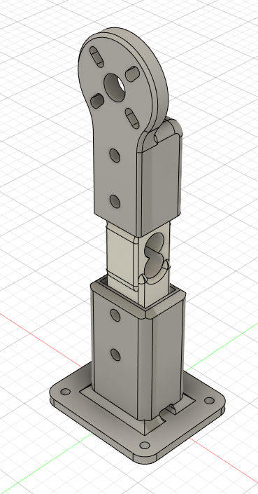
We started by designing and printing a simple load cell base and a motor mount to measure static thrust.
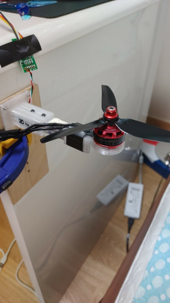
After calibrating the load cell with a 50g calibration weight and connecting the motor to an old ESC that was meant for RC planes, we printed the load cell output on the Arduino Serial Monitor.
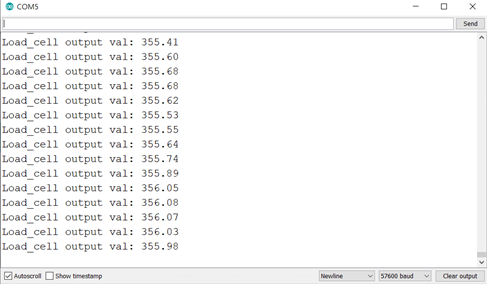
As you can see, we were only obtaining a maximum thrust of 356g… , which was far from the ~900g that we were expecting. We feel this could have been due to (i) the flexing of the plywood base, (ii) the low calibration weight that we used, and (iii) using a load cell meant for measuring ~20kg loads, instead of ~2kg/5kg load cells.
In the next post on the motor test stand project, we hope to have the initial design for the torque stand finished and have a better calibration procedure to get accurate thrust readings.
Stay tuned 🙂
Curious if you ever got anywhere on building a stand that does torque? RCbenchmark or now tytorobotics is massively expensive for what it is. Seems since they became tytorobotics they aren’t selling the boards outright either. So one can’t try and use their board but build the frame. I’ve thought about designing a real stand for iforce2d’s and outsource the code portion for integration of torque. Truthfully I could just run it in a parallel solution not integrated. Look forward to seeing what your group comes up with.
Hey Ryan. Apologies for the delay. TLDR: we haven’t measured torque yet.
We’ve split the design into two phases:
1. We are creating a library on github to send dshot commands to the ESC using an rpi pico (https://github.com/Guppy16/pico-dshot). I also have a branch that is able to request auto-telemetry data from the ESCs, though this is still a wip. This library is used as a submodule in a thrust test stand repo (https://github.com/Guppy16/pico-tts). This is also a wip, with the idea that this repo will be able to interface with the hx711 to measure thrust, torque.
2. We have created a prototype test stand similar to RC Benchmark. We’ve only attached one load cell to it to measure thrust. We had some issues with the motor mounts, so are planning to update and hopefully integrate more HX711s to measure torque.
We plan to blog these soon. Have you made any progress? I’d be interested to know which route you took in the end (parallel / integrated).
Kind regards,
Akash